Beam Solver#
In this tutorial we create a very minimal elasticity solver for solving for the displacement and von Mises stresses in a beam when under load.
We use the open source finite element software NGSolve for geometry modeling and solving and we use the ngsolve_webgpu python package for visualization of the solution fields.
Create the App#
We start by opening the console in a location where we want to create the app and then we run the following command:
python -m ngapp.create_app
we will be prompted to enter a module name an app title and the name of the App main class. We choose Beam Solver as the app title, and press enter on the automatically suggested module name beam_solver and the main class name BeamSolver.
Now we run the app in development mode with the command:
python -m beam_solver --dev
Creating the App Layout#
Now we open the file beam_solver/app.py in your IDE of choice.
First create a new QToolbar where we move the title into:
toolbar = QToolbar("Beam Solver", ui_class="bg-primary text-white")
Also we use a QCard to contain all the main layout:
self.component = Div(
    toolbar,
    QCard(
    QCardSection(
        self.button,
        self.counter_view),
    ui_flat=True)
)
Next we add another input and rename the two QInput to length and width. This should define our beam geometry. Also we change the QBtn to use a play icon and rename the callback function to solve:
self.button = QBtn(ui_color="primary",
                   ui_icon="mdi-play",
                   ui_flat=True,
                   ui_round=True,
                   ui_size="30px")
self.length = QInput(ui_model_value=5,
                     ui_label="Length (m)",
                     ui_style="width: 200px;")
self.width = QInput(ui_model_value=3,
                    ui_label="Width (m)",
                    ui_style="width: 200px;")
self.button.on("click", self.solve)
And change the layout of main component of the app:
self.component = Div(
    toolbar,
    QCard(
    QCardSection(
        Row(Col(Centered(self.length,
                         self.width)), Col(self.button))),
    ui_flat=True)
)
next implement a dummy solve function for testing the functionality:
def solve(self):
    length = float(self.length.ui_model_value)
    width = float(self.width.ui_model_value)
    # Placeholder for actual computation logic
    print(f"Solving beam with length {length} and width {width}")
Clicking the button should now print the length and width of the beam to the console.
We can set a global color palette for the app by adding the following line to the __init__ method of the BeamSolver class:
self.set_colors(primary="#0D47A1",
                secondary="#90CAF9",
                accent="#FF9800",
                dark="#212121",
                positive="#2E7D32",
                negative="#C62828",
                info="#0288D1",
                warning="#F57C00")
Next we add a WebgpuComponent to visualize the solution fields.
We will implement our own component that inherits from Div and contains a WebgpuComponent. This will allow us to customize the visualization component as needed.
class MyVisComp(Div):
    def __init__(self):
        self.webgpu = WebgpuComponent()
        super().__init__(self.webgpu,
            ui_style="border: 1px solid #ccc; border-radius: 5px;")

    def draw(self, mesh, displacement, vonMises):
        pass
and add it to the main card:
self.vis_comp = MyVisComp()
self.component = Div(
    toolbar,
    QCard(
    QCardSection(
        Row(Col(Centered(self.length,
                         self.width)), Col(self.button))),
    QCardSection(self.vis_comp),
    ui_flat=True)
)
Setting up Visualization#
In the final version we want to visualize the mesh as a wireframe, the displacement field as a deformation and the von Mises stress field as a color map. For this we start setting up the visualization with placeholders.
We implement the solve method to create a mesh and call the draw method of our new component.
def solve(self):
    import netgen.occ as ngocc
    import ngsolve as ngs
    length = float(self.length.ui_model_value)
    width = float(self.width.ui_model_value)
    r = ngocc.Rectangle(length, width).Face()
    r.edges.Min(ngocc.X).name = "left"
    r.edges.Max(ngocc.X).name = "right"
    maxh = 0.2 * min(length, width)
    geo = ngocc.OCCGeometry(r, dim=2)
    mesh = ngs.Mesh(geo.GenerateMesh(maxh=maxh))
    self.vis_comp.draw(mesh, None, None)
and in the draw method we render the mesh wireframe using the ngsolve_webgpu package:
def draw(self, mesh, deformation, vonMises):
    import ngsolve_webgpu as nw
    self.meshdata = nw.MeshData(mesh)
    wireframe = nw.MeshWireframe2d(self.meshdata)
    self.webgpu.draw([wireframe])
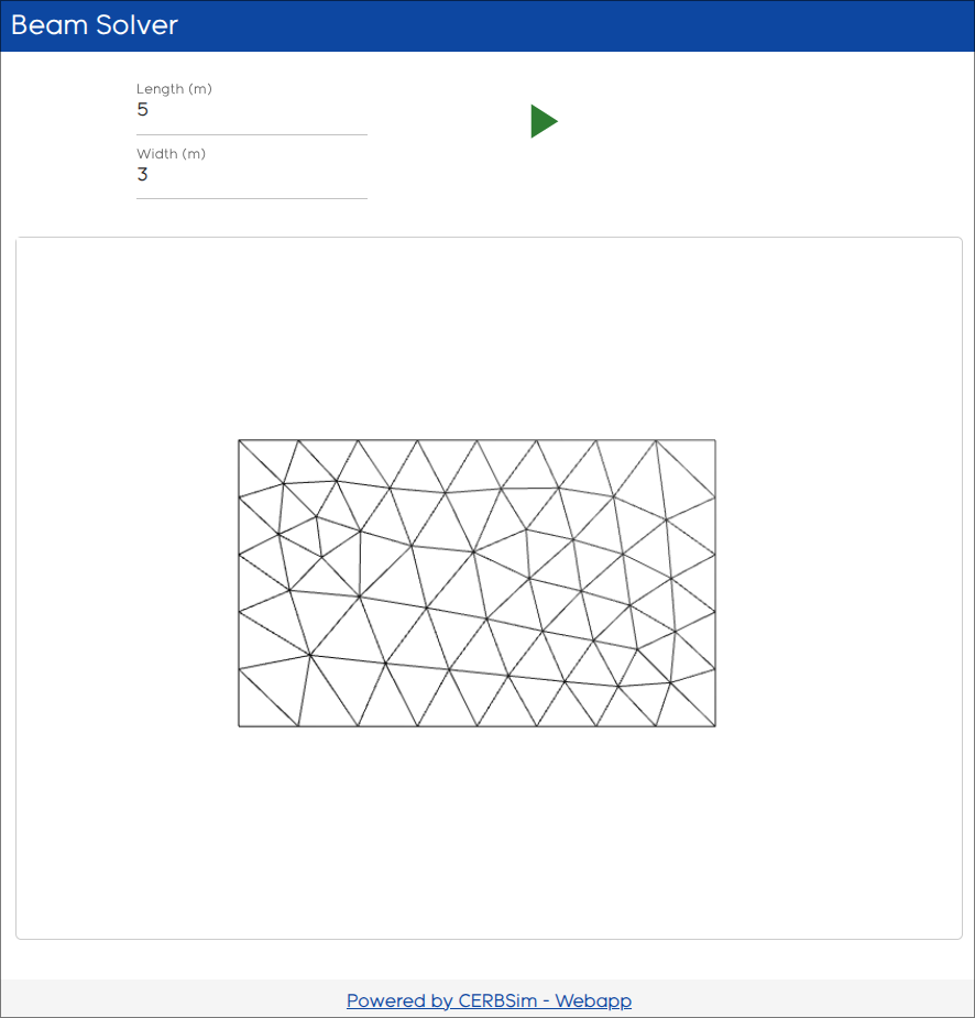
Now on clicking the run button we should see the mesh of the beam in the visualization area:
Next we want to deform the mesh with some given function, for testing we just deform the mesh by the value of the x coordinate in y direction:
def solve(self):
    ...
    deformation = ngs.CF((0, ngs.x, 0))
    self.vis_comp.draw(mesh, deformation, None)
and the draw method we apply the deformation to the mesh:
def draw(self, mesh, deformation, vonMises):
    import ngsolve_webgpu as nw
    self.meshdata = nw.MeshData(mesh)
    self.meshdata.deformation_data = nw.FunctionData(self.meshdata,
                                                     deformation,
                                                     order=5)
    wireframe = nw.MeshWireframe2d(self.meshdata)
    self.webgpu.draw([wireframe])
Similarily we set a placeholder for the von Mises stress field:
def solve(self):
    ...
    vonMises = ngs.y
    self.vis_comp.draw(mesh, deformation, vonMises)
and implement the renderer:
def draw(self, mesh, deformation, vonMises):
    import ngsolve_webgpu as nw
    self.meshdata = nw.MeshData(mesh)
    self.meshdata.deformation_data = nw.FunctionData(self.meshdata,
                                                     deformation,
                                                     order=5)
    vMdata = nw.FunctionData(self.meshdata, vonMises, order=5)
    colormap = nw.Colormap(colormap="viridis")
    renderer = nw.CFRenderer(vMdata, colormap=colormap)
    colorbar = nw.Colorbar(colormap)
    wireframe = nw.MeshWireframe2d(self.meshdata)
    self.webgpu.draw([wireframe, renderer, colorbar])
Implementing the Elasticity Solver#
def solve(self):
    import netgen.occ as ngocc
    import ngsolve as ngs
    length = float(self.length.ui_model_value)
    width = float(self.width.ui_model_value)
    r = ngocc.Rectangle(length, width).Face()
    r.edges.Min(ngocc.X).name = "left"
    r.edges.Max(ngocc.X).name = "right"
    maxh = 0.2 * min(length, width)
    geo = ngocc.OCCGeometry(r, dim=2)
    mesh = ngs.Mesh(geo.GenerateMesh(maxh=maxh))
    fes = ngs.VectorH1(mesh, order=3, dirichlet="left")
    u,v = fes.TnT()
    a = ngs.BilinearForm(fes)
    E = 210e9
    nu = 0.3
    mu = E / (2 * (1 + nu))
    lam = E * nu / ((1 + nu) * (1 - 2 * nu))
    strain = lambda u: ngs.Sym(ngs.Grad(u))
    stress = lambda s: lam * ngs.Trace(s) * ngs.Id(mesh.dim) + 2 * mu * s
    a += ngs.InnerProduct(stress(strain(u)), strain(v)) * ngs.dx
    a.Assemble()
    f = ngs.LinearForm(fes)
    surface = ngs.Integrate(ngs.CF(1), mesh.Boundaries("right"))
    force = ngs.CF((0, -1e5)) / surface
    f += force * v * ngs.ds("right")
    f.Assemble()
    u = ngs.GridFunction(fes)
    u.vec.data = a.mat.Inverse(fes.FreeDofs()) * f.vec

    deformation = ngs.CF((u[0], u[1], 0))
    vonMises = ngs.CF(
        ngs.sqrt(3 * ngs.InnerProduct(stress(strain(u)), stress(strain(u))))
    )
    self.vis_comp.draw(mesh, deformation, vonMises)
We see the mises stresses, the deformation is not visible because the deformation is very small compared to the size of the beam, we can scale it up by setting a deformation scale on the mesh data:
self.vis_comp.meshdata.deformation_scale = 1e5
We can now make this slider value changeable by adding a QSlider to the app:
    self.deform_slider = QSlider(ui_label=True,
                                 ui_model_value=1e5,
                                 ui_label_value="Deformation Scale: 1e5",
                                 ui_min=0,
                                 ui_max=1e5,
                                 ui_step=1e3,
                                 ui_style="width: 300px;")
    self.deform_slider.on_update_model_value(self.update_deformation_slider)
    ...
    self.component = Div(
        toolbar,
        QCard(
        QCardSection(
            Row(Col(Centered(self.length,
                             self.width)),
                Col(Centered(self.button,
                             self.deform_slider)))),
        QCardSection(self.vis_comp),
        ui_flat=True)
    )

def update_deformation_slider(self):
    self.deform_slider.ui_label_value = f"Deformation Scale: {self.deform_slider.ui_model_value:.1e}"
    if hasattr(self.vis_comp, "meshdata"):
        self.vis_comp.meshdata.deformation_scale = self.deform_slider.ui_model_value
        self.vis_comp.webgpu.scene.render()
and changing the line in the solve routine to
self.vis_comp.meshdata.deformation_scale = self.deform_slider.ui_model_value
Load / Save Functionality#
Each component that should be saved in a the app save procedure needs to be given a (namespace wise) unique id. So we add ids to the two input fields and to the webgpu member of the visualization component:
class MyVisComp(Div):
    def __init__(self):
        self.webgpu = WebgpuComponent()

...

    self.length = QInput(id="length",
                         ui_model_value=5,
                         ui_label="Length (m)",
                         ui_style="width: 200px;")
    self.width = QInput(id="width",
                        ui_model_value=3,
                        ui_label="Width (m)",
                        ui_style="width: 200px;")
The QInputs (and other quasar wrapped classes automatically store its data if given an id, for the deformation slider, we do not want it to be saved so we not give it an id.
The visualization webgpu component additionally needs to implement how to be stored and retrieved on load.
So first on each draw command we store the draw arguments in our component storage:
def draw(self, mesh, deformation, vonMises):
    self.storage.set("solution", (mesh, deformation, vonMises), use_pickle=True)
and we add an additional method that we call on component load:
class MyVisComp(Div):
 def __init__(self):
     ...
     super().__init__(...)
     self.on_load(self.__on_load)

 def __on_load(self):
     sol = self.storage.get("solution")
     if sol:
         self.draw(*sol)
This, after loading, looks if some solution is saved in the component storage and retrieves it. self.storage.get(“solution”) returns None if no solution is set.
And we add two new buttons to the toolbar for saving and loading the app state:
save_btn = QBtn(ui_icon="mdi-content-save",
                ui_flat=True).on_click(self.save_local)
load_btn = QBtn(ui_icon="mdi-folder-open",
                ui_flat=True).on_click(self.load_local)
toolbar = QToolbar(Heading("Beam Solver", 3),
                   QSpace(),
                   save_btn,
                   load_btn,
                   ui_class="bg-primary text-white")
Final State#
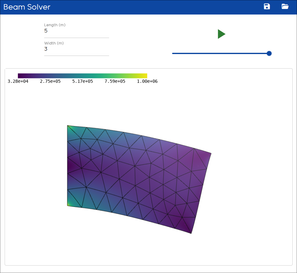
The final state of the app should look like this:
Deploy as Web Application#
For instructions on how to deploy the final app as a web application on github pages see Deploy App to Github Pages.